A NEW APPROACH OF SURFACE ENVELOPING, BASED ON THE DISCREETLY SURFACES REPRESENTATION, IN ORDER TO ALGORITHMIZE AND INFORMATIZE THE GENERATING TOOLS PROFILING
The machining improvement in the sense of machining precision increasing presume, more and more, the synthesis of models for generation errors prediction and adjustment by software using: analytical models [7], [16], modeling based on genetically algorithms [6], as so as, methods based on polynomial neural network (PNN) [2], using on machine measurement systems (OMM) [2], in order to adjust errors, the whole system being integrated in CAD/CAM/CAI systems.
It was developed [19] methods for errors adjustment by developing generating software for alternative tools movement, assuring an errors reduction up to 90% by decreasing the cutting force value.
It was developed algorithms [20] in order to optimize the tool position, for multi‑ax machine‑tools, integrated in CAD/CAM systems [5] for errors adjustment, using multi‑degree of freedom (multi‑DOF) sensors [7], also for curves and surfaces design by interactive 3D modeling, which are approximated by interpolation methods [17] in order to rebuild the surface form.
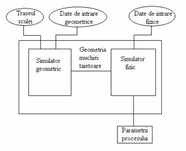
Fig. 1. Geometrical modeling based process simulator
It was developed geometrical simulators [10] linked with physical simulators based on cutting process modeling (see fig. 1). The process physical simulator consists in cutting force models for various existing situations. Each model based on empirical knowledge use as input data the geometrical simulator output data. In this way are obtained the cutting process parameters models starting from geometrical considerations. Often, the process simulator has an optimization module, which transmits information to machine‑tools kinematics chain in order to increase the productivity and to decrease the generating errors. In figure 2, is give an result obtained with this simulator type, comparative with experimental results.
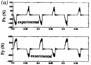
Fig. 2. Comparative between the process simulator result and experimental results
Based on the conjugated surfaces theory was developed methods for generation of surfaces expressed in discreetly form (digital gear tooth surfaces – DGTS) in 2D, as so as, in 3D, establishing solutions for enveloping surfaces determination – peripheral primary tools surfaces [3].
Fig. 3. Strategy for errors adjustment Fig. 4. Results comparison
Are established strategies for errors analyses and adjustment (see figure 3), applied at 2D and 3D modeling for involute teeth flank generation, [3], method which allow the generating tools profile drawing and in the same time the discreetly coordinates of tools generating movement (see figures 3 and 4).
Usually, the machining errors are defined on normal at machined surface as difference between this surface and the theoretically surface, discreetly expressed.
The error is detected only by surface measuring after machining.
Based on this concept is proposed an error estimation for cutting (DGTS). The machining errors are analyzed starting from the machined surface. The method makes a comparison between the two models: DGTS CAD model and a virtual model of measured surface of machined wheel teeth.
Error adjustment [1], [2], [3], [6], [13], [18]
It is known that the machined surface precision after a single correction is not total. Always remain a residual error.
So, is needed to establish an iterative scheme for machining error reduction, which will drive to increased time consumption. In current applications, the cutting process is repeated several times. If the result of first machining is processed and the data are inserted in numerical command is possible to make a more accurate machining.
The adjustment error is defined [3] as:
![]() .
(1)
.
(1)
They are also used the machine‑tools spatial errors adjustment [134] which solve the problem starting from the idea that the static errors affect the dimensional precision up tot 70% from the machine‑tool whole error.
In conclusion:
Exist an obviously attention regarding the prediction and adjustment by software of generation errors.
The integrated CAD/CAM/CAI systems allow to develop surfaces generating process with smaller errors.
For machines with more axes, are defined algorithms for spatial errors modeling, establishing analytical models for errors and systems for adjustment of these.
Are used genetically algorithms modeling based and methods based on polynomial neural network, using on machine measurement. Are interactive modeled 2D/3D surfaces curves which are approximated by interpolation methods in order of surface form rebuilding. At enveloping surface generation the tools shape correction regarding the generation result may be made using the geometrical modeling methods (Gohman, Willis, minimum distance, substitutive circles family, in‑plane generation trajectories, solid modeling) [21], [22], [23].
Bibliography
[1] Ahn, K.-G., Min, B.-K., Pasek, Z.J., Modeling And Compensation Of Geometric Errors In Simultaneous Cutting Using A Multi-Spindle Machine Tool, International Journal of Advanced Manufacturing Technology, 29, 2006, pag. 929–939.
[2] Cho, M.-W, Kim, G.-H., Seo, T.-I., Hong, Y.-C., Cheng, H.-H., Integrated Machining Error Compensation Method Using OMM Data And Modified PNN Algorithm, International Journal of Advanced Manufacturing Technology,43, 2006, pag. 1417-1427.
[3] Fulin, W., Chuanyun, Y., Tao, W.,, Yang, S., Zhao, G., A Generating Method For Digital Gear Tooth Surfaces, International Journal of Advanced Manufacturing Technology, 28, 2006, pag. 474–485.
[4] Fung, E.H.K., Chan, J.C.K., Modelling And Compensation Of Roundness Errors In Taper Turning, International Journal of Advanced Manufacturing Technology, 16, pag. 404–412, 2000
[5] Ispas, C., Pătraşcu, G., Prediction Of Shear Angle And Cutting Force In Milling Using 2D Simulation, International Conference On Manufacturing Systems, Bucharest, Published by Editura Academiei Române, ISSN 0035-4074, 2004, pag. 257-260.
[6] Jian, L., Hongxing, L., Modeling System Error In Batch Machining Based On Genetic Algorithms, International Journal of Advanced Manufacturing Technology,43, 2003, pag. 599-604.
[7] Lee, C.-K., Chen, C.-K., Mathematical Models, Meshing Analysis And Transmission Design For A Robust Cylindrical Gear Set Generated By Two Blade-Discs With Parabolic Cutting Edge, International Journal of Advanced Manufacturing Technology, C12, 2004, pag.1539–1553.
[8] Lee, J.H., Liu, Y., Yang, S.H., Accuracy Improvement Of Miniaturizing Machine Tool: Geometric Error Modeling And Compensation, International Journal of Advanced Manufacturing Technology,46, 2006, pag.1508-1516.
[9] Lee, T.S., Lin, Y.J., An Improved Sculptured Part Surface Design Method With Jerk Continuity Consideration For Smooth Machining, International Journal of Advanced Manufacturing Technology, 15, pag. 640–648, 1999
[10] Mu, Y. H., Monitorning a Sub‑Newton Cutting Force for Ultra‑Precision Machining. Int. J. Advance. Manufacturing Technologiy, 16, 2000, pp. 229‑232
[11] Rao, V. S., Yoon, K.Y., Minimization Of Transmission Error In Helical Gears. În: Journal of Mechanical Engineering, Proc. Instn. Mech. Engrs., Vol. 215, Part. C, 2001, pag. 447‑459.
[12] Rao, V.S., Rao, P.V.M., Tool Deflection Compensation In Peripheral Milling Of Curved Geometries, International Journal of Advanced Manufacturing Technology,46, 2006, pag. 2036-2043.
[13] Ratchev, S., Liu, S., Huang, W., Becker, A.A., An Advanced FEA Based Force Induced Error Compensation Strategy Inmilling, International Journal of Advanced Manufacturing Technology,46, 2006, pag. 542-551.
[14] Ratchev, S., Liu, S., Huang, W., Becker, A.A., Error Compensation Strategy In Milling Flexible Thin-Wall Parts, International Journal of Advanced Manufacturing Technology,162-163, 2005, pag. 673-681.
[15] Ratchev, S., Liu, S., Huang, W., Becker, A.A., Milling Error Prediction And Compensation In Machining Of Low-Rigidity Parts, International Journal of Advanced Manufacturing Technology,44, 2004, pag. 1629-1641.
[16] Shi, M., Zhang, Y. F., s.a., Triangular Mesh Generation Employing a Boundary Expansion Technique, Int. J. Advance. Manufacturing Technologiy, 30, 2006, pp. 54‑60
[17] Suh, S.-H., Lee, E.-S., Jung, S.-Y., Error Modelling And Measurement For The Rotary Table Of Five-Axis Machine Tools, International Journal of Advanced Manufacturing Technology, 14, 1998, pag. 656-663.
[18] Yang, S.-H., Kim, K.-H., Park, Y.K., Lee, S.-G., Error Analysis And Compensation For The Volumetric Errors Of A Vertical Machining Centre Using A Hemispherical Helix Ball Bar Test, International Journal of Advanced Manufacturing Technology, 23, 2004, pag. 495–500.
[19] Sabri, T. E., Can, C., Cutting Force Induced Error Elimination Method for Turning Operation, International Journal of Advanced Manufacturing Technology, 170, 2005, pag. 192‑200.
[20] Lin, J. C., Tai, C. C., Accuracy Optimization for Mold Surface Profile Milling, International Journal of Advanced Manufacturing Technology, 15, 1999, pag. 15‑25.
[21] Oancea, N., Generarea suprafetelor prin infasurare. Vol. I. Teoreme fundamentale, Editura Fundatiei Universitare Dunarea de Jos, ISBN 973-627-106-4, ISBN 973-627-170-6, 2003;
[22] Oancea, N., Generarea suprafetelor prin infasurare. Vol. II. Teoreme complementare, Editura Fundatiei Universitare Dunarea de Jos, ISBN 973-627-106-4, ISBN 973-627-107-2, 2004;
[23] Oancea, N., Baicu, I., Teodor, V., Dima, M., Generarea suprafetelor prin infasurare. Vol III. Complemente, Editura Fundatiei Universitare Dunarea de Jos -Galati, ISBN973-627-106-4, ISBN973-627-239-7, 2005.